Today I’m going to explain a simple way to create a network topology for your home needs. The solution provided would probably good enough for small offices as well, while bigger networks will need professional solutions.
The topology the we are going to draw are to be considered as references for small networks that are slowly increasing in size. For example a few years ago we generally saw one computer per house, maybe with a modem connection to the Internet, but today we have more than one PC, smartphones, tablets, laptops, media centers, TV and small servers all connected to the internet in small/big home network.
Therefore I see more and more often people struggling to remember what is connected to what or even what is supposed to be stored where or which name or IP are assigned to what. Summarizing… A mess…
So in my research to solution to this problem I’ve thought to try to use something freely available to many and simple to use: LibreOffice Draw.
I thought as well that it would have been nice to be able to use those nice Cisco icons that you can find in products like Cisco Packet Tracer and I’ve surprisingly discovered that Cisco has made available those icons to everybody in many different formats.
Thanks to this we can now start preparing our home-made network topology:
1.download and install Libreoffice from this link;
2. download the Cisco icons in JPG format at this link and uncompress the file in a folder of your choice;
3. run Libreoffice Draw;
4. Choose the menu Tools -> Gallery
5. Now we are going to create a specific Theme by clicking on the button New Theme (this will open a new window);
6. In the new window we can put a nice title (ie. “Cisco”) and then we need to choose the tab called Files;
7. Now we choose Find and go to the folder where we decompressed the Cisco icons and then choose the path with OK;
8. All the icons will be imported (it will take a few seconds) and then you can confirm with OK;
9. The icons have been imported but now you will need to have the icons window and the editing window both visible. To do this move the theme bar to the left or right of the screen. In this way you will see the editing area and the icons visible.
10. Now you can start adding icons to the main area and by double clicking on them you’ll be able to write a multiline description (like the hostname and the IP address).
See an example I’ve quickly drawn below:
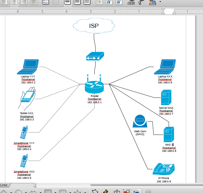
Sample Network Topology
Now you can have all the information you want at hand and maybe do proper planning on your network for future expansion!
UPDATE 30/07/2014: as commented by Mark Oellermann (see comments below), he has made available under a Creative Commons Attribute-ShareAlike V3 license which allows commercial and non-commercial use, modification and redistribution as long as the terms of the license are met. These are available at: http://www.vrt.com.au/downloads/vrt-network-equipment


Hi Stefano, as well as the Cisco shapes, I made these http://www.vrt.com.au/downloads/vrt-network-equipment and have recently added some of the logical symbols as well, allowing you to do the same, but with native, scalable, LibreoOffice vector shapes instead of bitmaps.
Thank you very much Mark for bringing your piece of work here! I’m going to update my article! Nice drawings btw!
Hi,
I downloaded the VRT symbol .oxt, and installed it using the Extension Manager in Draw 3.5, but I can’t figure out how to use the symbols. They don’t show up in the Drawing toolbar with the built-in symbols, they don’t show up in the gallery, and a this page is about the most useful google result so far in a search for how to use symbols from an oxt in Draw.
So, what’s the secret for getting access to them, please?
If Mark sees this, I’d like to suggest the addition of symbols for a terrestrial point-to-point wirelss link. We’re using Ubiquiti radios that have their own IPAs at each end, so a symbol like Cisco’s “wireless bridge” is useless for depicting the installed equipment. Something like a small, horizontally-aimed dish would give a better impression of what’s installed, and what it’s for, than using the omnidirectional-looking AP symbols.
Thanks,
Ran
Hello Ran,
thank you for your feedback on my article. Please note that it was focused on importing .jpg images from the Cisco website into the gallery, not .oxt. Anyway, I’ve tried to import the VRT symbols into my Draw (version 4.5) and it showed up without any issue at all… Have you got any error message?
Thanks,
Stefano
Interesting post! I sometimes read your blog and find out for myself something new.
I think I need to share this in facebook. My friends will also be interested.
Thank you.